|
 |
|
|
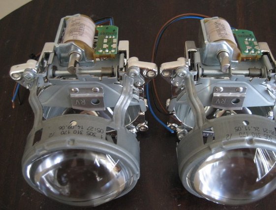
What's Included
What You Need
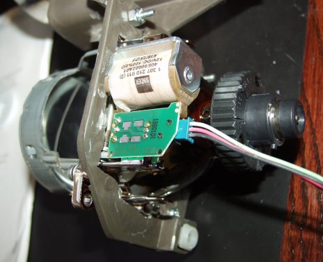
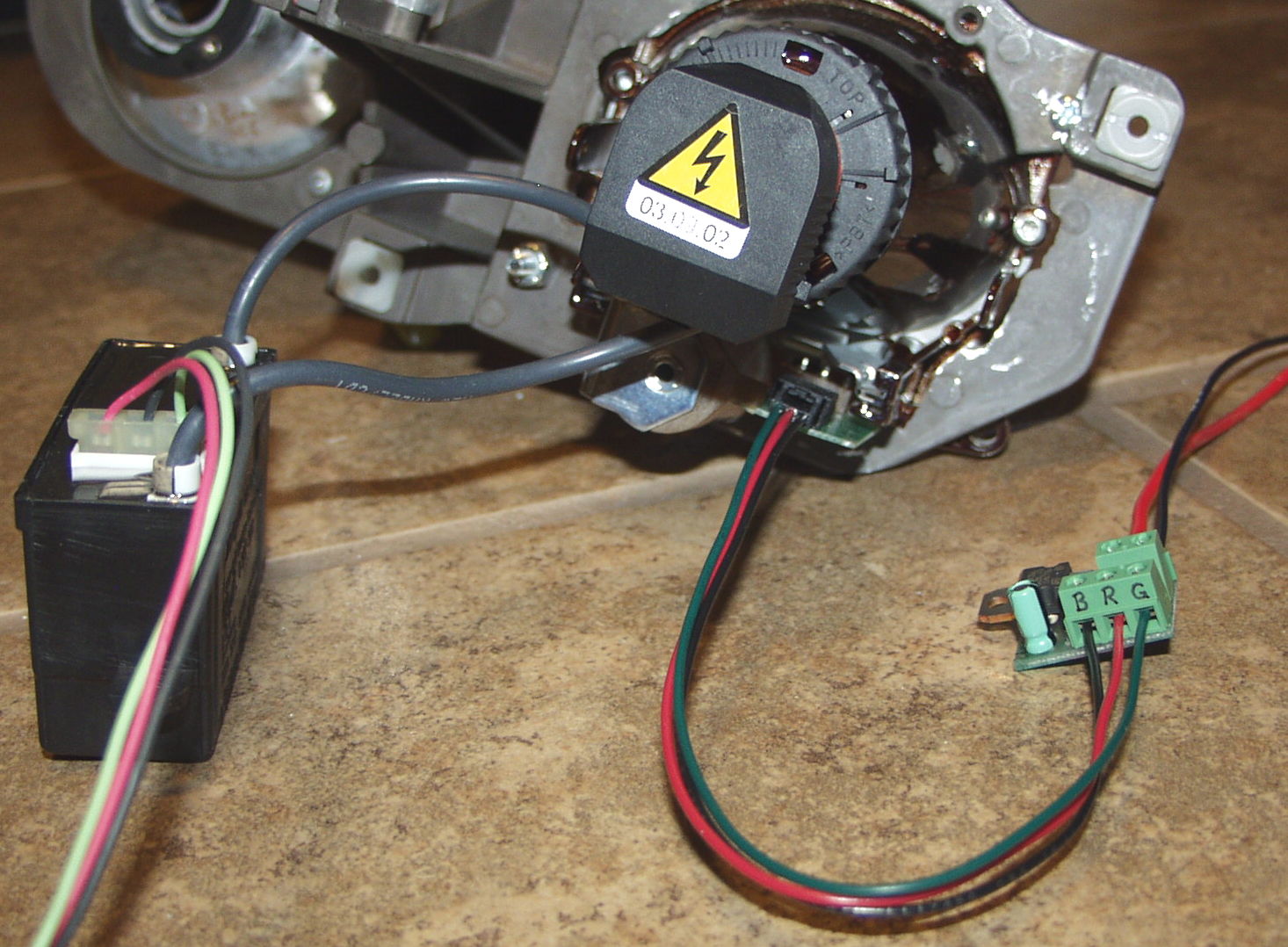
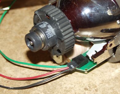
Wiring Instructions
|
|
|
|
|
|
|
|
Testing
Now that you've connected your controllers to your projector solenoids, it's a good idea to test your new system to make sure the controllers are connected properly and the solenoids are operating correctly. To do this, turn on your high beams to activate the solenoids. The shutters should open quickly and forcefully, with a loud thump. After this, with the high beams remaining on, you should be able to close the shutters by hand, and they should either not reopen at all on their own, or only open very weakly. If you can't close a shutter by hand without it popping open with as much force as initially, then something's wrong, and the "pull" solenoid is being powered continuously, which is bad since it will eventually overheat.
Headlight Wiring
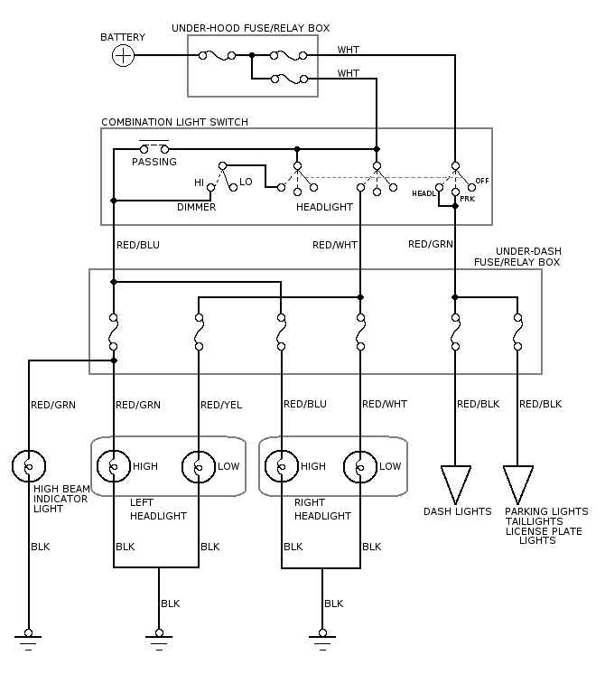
This diagram shows the electrical diagram for the Integra's headlights, in stock form. Other vehicles should be similar.
|
| Integra Headlights |
As you can see, this car has the headlights arranged in a positive-switched circuit, where the positive connections to the headlights are switched on and off, and the headlights' ground connections are always connected. This is probably the most common arrangement. Some cars have a negative-switched arrangement for some reason, so watch out for that on your car.
Like many cars, this car forgos using any relays on the headlights, and switches them on directly with the headlight switch. This is fine for regular halogen bulbs, but not for HID systems because of their very high current draw during warm-up. Also, you can see the multiple levels of fusing; some main fuses (100A, 50A) in the under-hood fuse box, and some smaller (10A) fuses for each individual bulb in the under-dash fuse box.
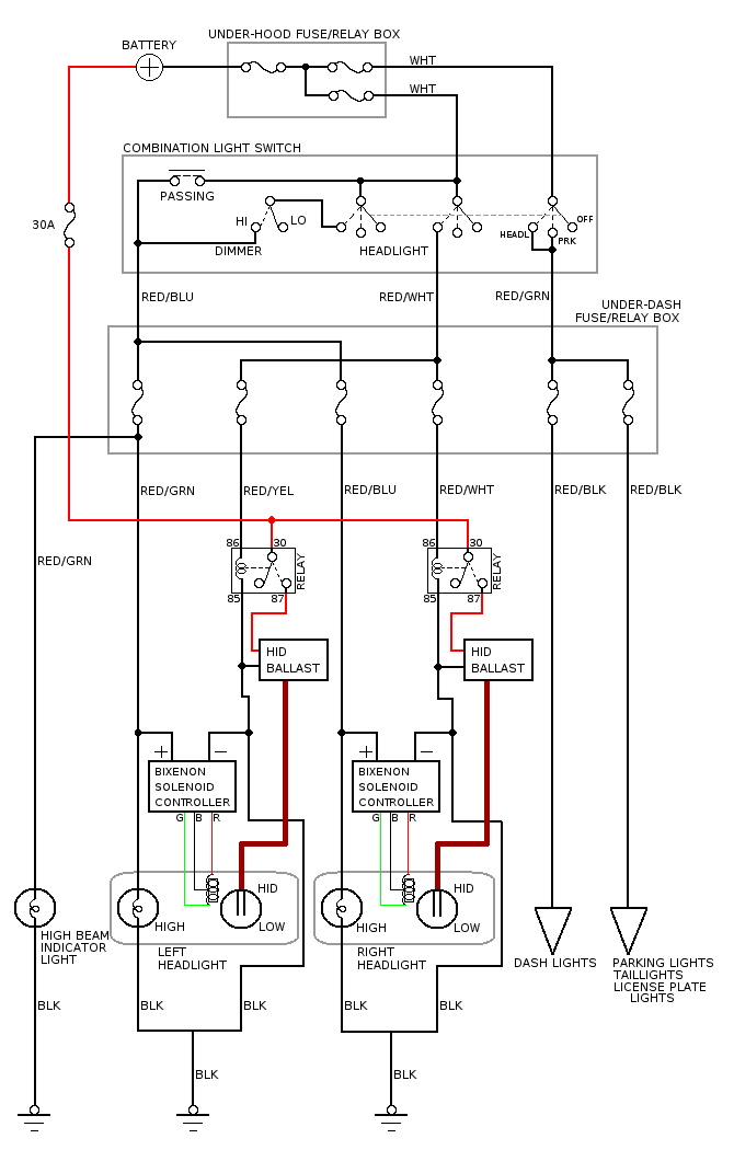
This next diagram shows how this system should be modified for HID bulbs and my bixenon solenoid controllers.
|
| Integra Headlights Modified for HID |
In this circuit, relays have been added to switch power to the HID ballasts, along with an appropriate fuse and connection straight to the battery. In addition, the bixenon solenoid controllers have been added, and its labeled connections are shown. The B, R, and G connections are connected to the matching colored wires from the Bosch bixenon solenoid, the "-" connection is connected to a ground wire, and the "+" connection is connected to the high-beam positive wire. This way, the solenoid will be activated when the high beams are switched on.